To make a DC brushless motor to rotate, it is necessary that the constant magnetic field of the rotor be entrained by the rotating electromagnetic field of the stator, as in a conventional DC motor.
The rotation of the stator magnetic field is carried out by commutating the windings using an electronic control unit. The design of a brushless motor is similar to the design of a AC synchronous motor. If you connect the brushless motor to a three-phase AC network that satisfies the electrical parameters of the motor, it will work.
A certain switching of the windings of a brushless motor allows it to be controlled from a DC source. To understand how to create a commutation table for a brushless motor, it is necessary to consider the control of an AC synchronous machine.
Synchronous motor
The synchronous machine is controlled from a three-phase alternating current network. The motor has 3 electrical windings, offset by 120 electrical degrees.
If start a three-phase motor as a generator, a constant magnetic field will induce an EMF in each of the motor windings.
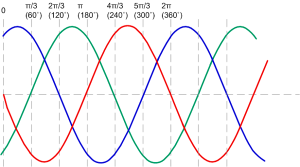
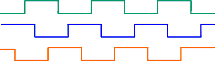
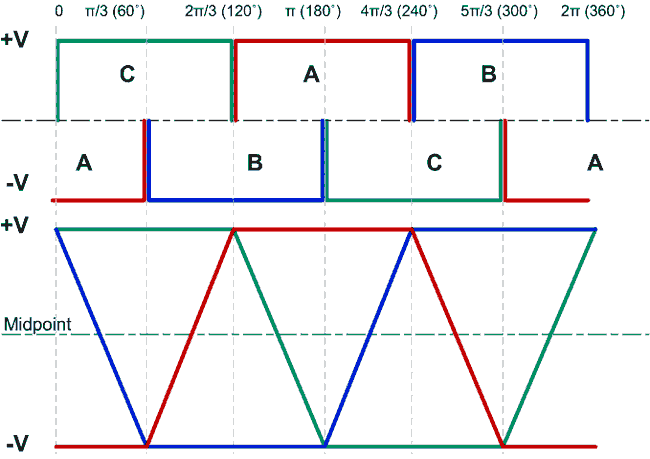
The motor windings are distributed evenly, a sinusoidal voltage will be induced on each of the phases and these signals will be shifted among themselves by 1/3 of the period (Fig. 1). The shape of the EMF changes as a sinusoidal quantity, the period of the sinusoid is 2π (360 deg.), since we are dealing with electrical quantities (EMF, voltage, current), the period is measured as electrical degrees.
When three-phase voltage is applied to the motor, at each moment of time there will be a certain current value on each of the windings.
Each winding generates a magnetic field vector proportional to the current in the winding. The resulting magnetic field vector is the sum of the magnetic field vectors of the three windings. Since over time the current in the motor windings changes as a sinusoidal wave, the magnitude of the magnetic field vector of each winding changes, and the resulting total vector changes the angle of rotation, while the magnitude of this vector remains constant.
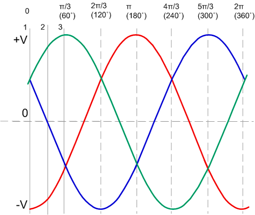
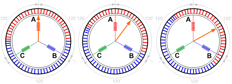
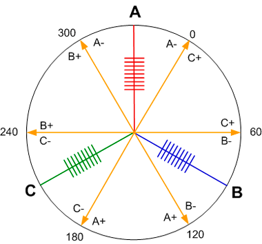
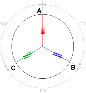
Figure 2 shows one electrical period of a three-phase motor. This period is marked with 3 arbitrary points. Let’s plot this period (360 electrical degrees) on a circle to construct a magnetic field vector at each of these points. Let's place 3 motor windings shifted by 120 electrical degrees relative to each other (figure 3).
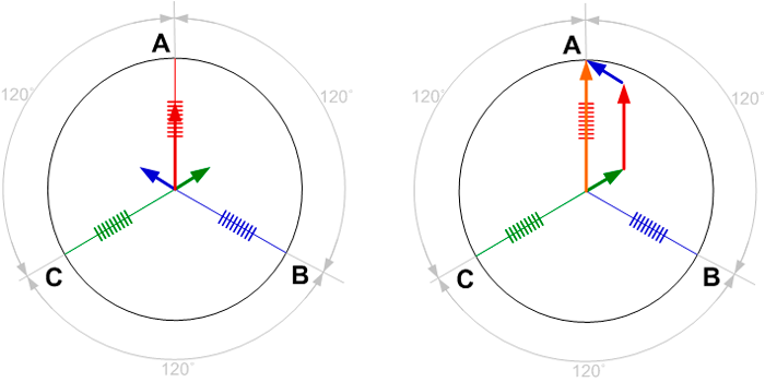
A magnetic field vector created by the motor winding is constructed along each phase. The direction of the vector is determined by the direction of the direct current in the winding. If the voltage applied to the winding is positive, then the vector is directed in the opposite direction from the winding; if negative, then along the winding. The magnitude of the vector is proportional to the voltage on the phase at a given point.
To obtain the resulting magnetic field vector, it is necessary to add the vector data according to the law of vector addition.
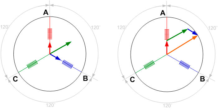
The construction is similar for the second and third points.
So, over time, the resulting vector smoothly changes its direction. Figure 5 shows the resulting vectors and shows the complete rotation of the stator magnetic field in one electrical period.
This electric magnetic field vector is followed by the magnetic field of the permanent magnets of the rotor at each moment of time (figure 6).
This is how an AC synchronous machine works. Having a direct current source, it is necessary to independently form one electrical period with a change in current directions on three motor windings. Since a brushless motor is the same in design as a synchronous motor and has identical parameters in generator mode, it is possible to start from figure 5, which shows the generated rotating magnetic field.
DC voltage
The DC source has only 2 wires “+” and “-”, which means that it is possible to supply voltage to only two of the three windings. It is necessary to approximate Figure 5 and highlight all the moments at which it is possible to connect 2 phases out of three.
The number of permutations from set 3 is 6, therefore, there are 6 options for connecting the windings.
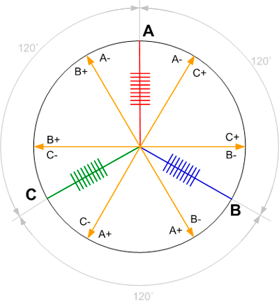
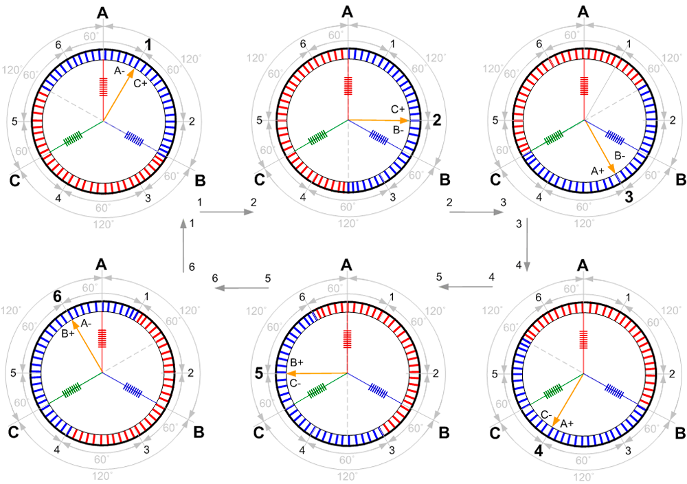
Let's draw possible switching options and highlight the sequence in which the vector will rotate further step by step until it reaches the end of the period and starts over and consider the electric period from the first vector.
Figure 5 shows that when controlling a three-phase sinusoidal voltage, there are many vectors that rotate smoothly over time, and when switching with direct current, it is possible to obtain a rotating field of only 6 vectors, that is, switching to the next step must occur every 60 electrical degrees. The results from Figure 7 are summarized in the Table 1.
Voltage +
Voltage -
Winding not connected
w
u
v
w
v
u
u
v
w
u
w
v
v
w
u
v
u
w
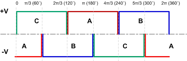
The appearance of the resulting control signal in accordance with Table 1 is shown in Figure 8. Where -V is the switching to the minus of the power supply (GND), and +V is the switching to the plus of the power source.
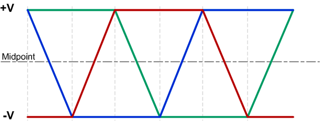
However, the real picture from the motor phases will be similar to the sinusoidal signal from Figure 1. The signal forms a trapezoidal shape, since at moments when the motor winding is not connected, the permanent magnets of the rotor induce an EMF on it (Figure 9).
Design features
As discussed earlier, one electrical period of 360 electrical degrees is formed in 6 winding switchings. It is necessary to relate this period to the actual angle of rotation of the rotor. Motors with one pair of poles and a three-tooth stator are used extremely rarely. Motors have N pairs of poles.
Figure 10 represents motor models with one pair of poles and two pairs of poles.
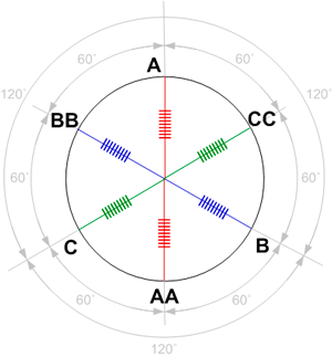
A motor with two pairs of poles has 6 windings. Each of the windings is paired. Each group of 3 windings is offset by 120 electrical degrees. Figure 11b shows one period for 6 windings. The windings A-AA, B-BB, C-CC are interconnected and structurally represent 3 wires - phase terminals. To simplify the figure, the connections are not shown, but it is assumed that A-AA, B-BB, C-CC are the same.
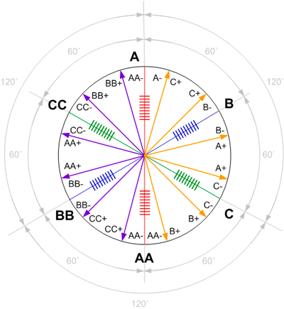
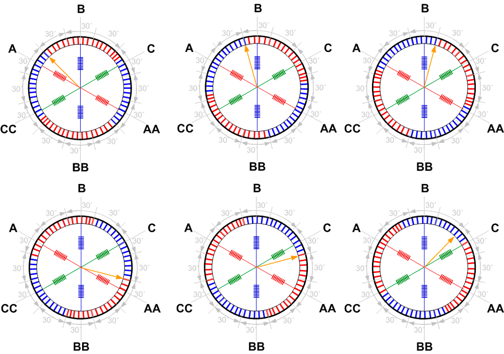
Figure 11, based on the data in Table 1, shows the vectors for one and two pairs of poles.
Figure 12 shows the vectors created by 6 commutations of motor windings with one pair of poles. The rotor consists of permanent magnets, in 6 steps the rotor will rotate 360 mechanical degrees.
The figure shows the final positions of the rotor. Rotor rotates from the previous to the next switched state in the intervals between two adjacent positions. The next changeover must occur when the rotor reaches this end position. The rotor will tend to a new position, so that its magnetic field vector becomes co-directed with the electromagnetic field vector of the stator.
If the motor has N pairs of poles, then N electrical periods must pass to complete one full mechanical revolution.
A motor with two pairs of poles will have two magnets with poles S and N, and 6 windings (figure 13). Each group of 3 windings is offset from each other by 120 electrical degrees.
Detecting the rotor position of a DC brushless motor
As noted earlier, for the motor to rotate, it is necessary to apply voltage to the required stator windings at the certain moments. Voltage must be applied to the motor windings depending on the position of the rotor, so that the stator magnetic field always leads the rotor magnetic field. An electronic control unit is used to detect the position of the motor rotor and winding switching. Detecting the rotor position is possible in several ways:
• Using Hall sensors
• Analysis of back EMF
Usually, manufacturers equip the motor with Hall sensors at a factory, so this is the most common control method. Switching the windings in accordance with back EMF signals allows abandoning the sensors built into the motor and use information from the unconnected phase of the motor, which will be induced by the magnetic field of the back EMF.
Control of DC brushless motor with Hall sensors
Hall sensors are the most common way to monitor the rotor position of a DC brushless motor to commutate its windings.
Since there are 6 states of the magnetic field vector, it is needed 3 Hall sensors to represent one absolute position sensor with a 3-bit output. Hall sensors are installed in the same way as windings, offset from each other by 120 electrical degrees. This allows the rotor magnets to be used as an actuating element of the sensor.
To make the motor to rotate, the magnetic field of the stator must be ahead of the magnetic field of the rotor. The position when the rotor magnetic field vector is co-directed with the stator magnetic field vector is final for this commutation. It is the moment when, theoretically, the switch to the next combination should occur in order to prevent the rotor from hanging in a stationary position. But if delve deeper into the process, it becomes clear that the switch should happen much earlier. When the magnetic field vectors of the rotor and stator are co-directed, the motor torque is already zero. With this control, the motor will not rotate with maximum torque, but with its remnants. In addition, it must be taken into account that the current will not increase instantly after switching, which means that at high rotation speeds the switching must be carried out even earlier. In order for the motor to operate in optimal torque mode, it is needed to strive to maintain an average of 90 degrees between the rotor and stator flux (stator current).
Now let's compare the signals from the Hall sensors with the combination of phases that need to be switched (Table 2)
Hall sensors
Motor phases
Rotor position
Ha
Hb
Hc
A
B
C
0
0
0
1
0
-
+
1
0
1
+
-
0
1
0
0
+
0
-
1
1
0
0
+
-
0
1
0
-
+
0
= 360/N
0
1
1
-
0
+
A signal shifted by 1/6 of the period (i.e. 60 electrical degrees) arrives from the the Hall sensors, when the motor rotates steadily (figure 14).
Control of DC brushless motor using BEMF
There are DC brushless motors without Hall sensors. The rotor position of such motors can be detected using EMF signal in the not connected phase of the motor. For every moment of time, voltage “+” is applied to one of the phases, “-” of a power supply to the other, and one of the phases remains not connected. While rotating, the magnetic field of the rotor induces an EMF in the not connected winding. The voltage on this phase changes during rotation.
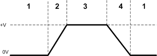
The signal from the motor winding is divided into 4 stages:
1. Winding is connected to 0
2. Winding is not connected
3. The winding is connected to the + supply voltage
4. Winding is not connected
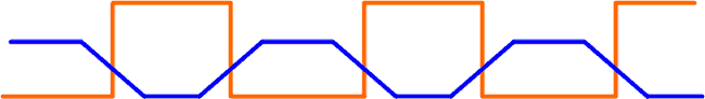
By comparing the signal from the phases with the control signal, it is clear that the moment of transition to the next state can be detected by the intersection of the midpoint (half of the supply voltage) with the phase that is not currently connected (Figure 16).
After detecting an intersection, it is necessary to make a pause and turn on the next state. Based on this figure, an algorithm for switching winding states was compiled (Table 3).
Current state
A
B
C
Next state
1
-
Waiting for the midpoint to cross from + to -
+
2
2
Waiting for the midpoint to cross from - to +
-
+
3
3
+
-
Waiting for the midpoint to cross from + to -
4
4
+
Waiting for the midpoint to cross from - to +
-
5
5
Waiting for the midpoint to cross from + to -
+
-
6
6
-
+
Waiting for the midpoint to cross from - to +
1
The intersection of the midpoint is easiest to detect with a comparator; the midpoint voltage is supplied to one input of the comparator, and the current phase voltage is supplied to the second.
The comparator is triggered when the voltage passes through the midpoint and generates a signal for the microcontroller.
Signal processing from motor phases
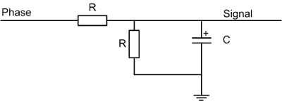
However, the signal from the phases when regulating the PWM speed differs in appearance and has a pulsed nature, in such a signal it is impossible to detect intersection with the midpoint. So, the signal should be filtered with an RC filter to obtain an envelope curve, and also divided according to the requirements of the comparator. As the duty cycle increases, the PWM signal will increase in amplitude.
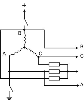
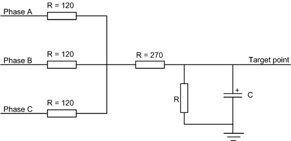
When using a circuit with a midpoint, the signals from the phases are received through current-limiting resistors and combined.
Due to PWM, the midpoint voltage is not constant. The signal also needs to be filtered. The midpoint voltage after smoothing will be quite large (about the motor supply voltage), it must be divided by a voltage divider to half of the supply voltage.
After the signal passes through the filter, the oscillations are smoothed out and a flat voltage is obtained relative to which the intersection of the back EMF can be detected.
The midpoint will change its value depending on the voltage (PWM duty cycle), as well as the signal envelope curve.
The received signals from the comparators enter the control microcontroller, which processes them.
Hall sensors vs BEMF
A sensorless method for determining the rotor position based on EMF may not work well in a certain range of low rotation speeds, where the EMF is small. In these cases, all the simplest sensorless systems commutate phases “blindly”, without knowing the position of the rotor, on the assumption that the rotor will follow the commutation - a stepper operating mode. This method is successfully used in such devices as fans or model aircraft propellers, where the load torque is low at low speeds. If the load is large and inertial, this control mode is not suitable, since the torque will be unstable, the motor may not start at all or may fall out of synchronization. If it is necessary to develop maximum torque at low speeds, it is necessary to apply a current vector with the desired phase relative to the rotor position. In this case, the option of controlling a DC brushless motor using Hall sensors is more preferable. The sensors provide a signal and provide information about the position of the rotor at zero speed inclusive, so the motor immediately operates in the optimal output torque mode.
You can choose a DC brushless motor with Hall sensors, that is best suited for your project on our website in the section
“DC brushless motors (BLDC)”.
DC brushless motor controllers for BLDC motors with Hall sensors are available to be purchased in our online store shop.smd.ee
 ES
ES